Posts

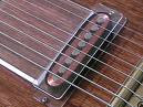
anisotropic strip LCD zebra

Image
The anisotropic strip on the LCD is technically known as an elastromeric connector, but usually referred to as a zebra strip. If you examine it closely under a strong magnifying glass or a low power microscope, you’ll see alternating bands of conductive and insulating material, usually something like graphite loaded rubber for the conductive material and unloaded rubber for the insulating material. The graphite loaded rubber gives that portion of the strip a darker colour. Thus, you have alternating light and dark bands, similar to what a zebra looks like.
Image
The Physics of Electric Guitar Pickups Electric guitar pickups are devices that are used to create an electric current corresponding to the mechanical vibration of the steel strings on a guitar. Electric guitar pickups are often considered to be similar in operation to microphone, but pickups and microphones are, indeed, different devices. A microphone has a small diaphragm that is vibrated by sound waves, a permanent magnet, and a wire coil that is attached to the diaphragm and moves inside the magnetic field of the magnet. An electric guitar pickup, on the other hand, has the coil wound around the permanent magnet and a steel string that moves within the magnetic field of the permanent magnet. In both cases, a change in magnetic flux (a measure of the magnetic field strength) through the coil induces a current in the coil. The major difference between the two is that only the vibration of the steel strings is picked up by the electric guitar pickup, not sound. This leads to some dist...

web resources for begineers in embedded

Link Description About WEB ster A description of this site, contact information, and other useful information about Webster. Art of Assembly Book The most popular on-line assembly language reference in the world! Join the thousands and thousands of people who've discovered the fastest and easiest way to learn assembly language programming! High Level Assembly SourceForge Download Page The evolution of assembly language! Now you can write real assembly language programs without all the disadvantages of writing code in assembly language. Now you can write applications in true assembly code as efficiently as writing code in a high-level language. NEW! The HLA Standard Library v3.x SourceForge Download Page The most popular component of the High Level Assembler (HLA) has always been the HLA Standard Library. Check out the bran...

MY double D contd..

DAY 2 9:38 AM 6/27/2008 > yesterday the following were purchased -Capacitor box , all the reqd pf s , it was lacking some of the reqd values soo i added the values .. still some are missing line 47kpf etc ,plan to purchase today ... -IC CD 4049 , L -FETs j112 [as a replace ment for the J109 ] ,vendor told it should match the actual one upto 90% -Ribbon wire 6 core , 1 mtr , for the pots , -Mic jack and socket , for testing phase i am using a cheap mic jack 10 Rs and Mic socket :) -Electorlytics 10uf and 4.7uf ,diodes 1N4007 [for the soldering iron ..heh not part of original double d] -A cutter and Stripper , to be used wire and leg cutter -A soap box ...wait its a temporary cabinet to hold the SIX POTS ,and the mic jack ..battery etc what so-ever - also a thin soap box is . easy to drill ... with the mosquito coils ..my new trick The already exiting parts - resistor box , still some missing values like 1 M , 2.2 M , 220K etc soo i have to add today -sol...

DIY distortion unit for guiter-MY Double D

Project Log : -------------------------------- Name: My Double D -------------------------------- -------------------------------- The Idea : -------------------------------- I wanted to make a decent distortion pedal for my guitar , at a lesser expense . Also wanted some thing of small foot print. Online i got good reviews for the Double D . The simple design looked great , component count was less and .only 1 chip! CD 4049 ... power packed with six inverters . The URL : http://www.runoffgroove.com/doubled.html Then i checked the sound clips ..online both modes sounded as pretty nice . The kit should not cost more than 180Rs. leaving the cabinet and accessories . ------------------------------------------------------------------------------------------------ DAY 1 12:46 PM 6/26/2008> [Thursday] -today is the first day i just did the shopping[sp road] .. i hope all components are in stock components alone -getting the J-FETs was a pain ..i rep...

Interfacing DC motors with microcontroller

Image
DC motors are always preffered over stepper motors. There are many things which you can do with your DC motor when interfaced with a microcontroller. in this tutorial we will learn to interfacing a DC motor with a microcontroller. Usually H-bridge is preffered way of interfacing a DC motor. These days many IC manufacturers have H-bridge motor drivers available in the market like L293D is most used H-Bridge driver IC. H-bridge can also be made with the help of trasistors and MOSFETs etc. ►Working Theory of H-Bridge The name "H-Bridge" is derived from the actual shape of the switching circuit which control the motoion of the motor. It is also known as "Full Bridge". Basically there are four switching elements in the H-Bridge as shown in the figure below. As you can see in the figure above there are four switching elements named as "High side left", "High side right", "Low side right", "Low side left". When these switches are tur...

Nokia dot Matrix LCD Interfacing with 89c51( 8051 core)

Image
The Nokia 3310 LCD is based on a PCD8544 48x84 pixels matrix LCD controller Pin Diagram given above .. Schematic: ---------------------------- AT89C51 PROGRAM CODE ;Program for Nokia 3310 LCD PCD8544 48x84 pixel SCK BIT P1.7 SDIN BIT P1.6 D_C BIT P1.5 SCE BIT P1.4 RES BIT P1.3 ORG 0000H AJMP MAIN ORG 0030H MAIN: MOV SP,#60H MOV P1,#00H CLR C CALL RESET CALL LCD_INIT HERE: CALL CLEAR_RAM MOV DPTR,#MESSAGE CALL LCD_STRING CALL DELAYS CALL CLEAR_RAM MOV DPTR,#IMAGE CALL DISPLAY CALL DELAYS AJMP HERE DELAYS: ;1s DELAY MOV R5,#10 D1: CALL DELAY DJNZ R5,D1 RET DELAY: ;100ms DELAY SETB PSW.4 MOV R7,#200 HDH: MOV R6,#100 HD: NOP NOP NOP DJNZ R6,HD DJNZ R7,HDH CLR PSW.4 RET RESET: ; RESET SETB SCE SETB RES CLR RES CALL DELAY SETB RES RET LCD_INIT: ;INITALIZE LCD MOV DPTR,#LCDCODE1 CALL LCD_IN CALL CLEAR_RAM MOV R1,#00H ;Y MOV R2,#00H ;X CALL CURSOR RET LCD_IN: MOV A,#00H MOV R6,#00H LOOP3: INC R6 MOVC A,@A+DPTR CJNE A,#2FH,NEXT3 RET NEXT3: CALL LCD_COM MOV A,R6 AJMP LOOP3 DISPLAY: ;DISPLAY IMA...

What is the difference between a von Neumann architecture and a Harvard architecture?

Applies to: All Processor Cores Harvard architecture has separate data and instruction busses, allowing transfers to be performed simultaneously on both busses. A von Neumann architecture has only one bus which is used for both data transfers and instruction fetches, and therefore data transfers and instruction fetches must be scheduled - they can not be performed at the same time. It is possible to have two separate memory systems for a Harvard architecture. As long as data and instructions can be fed in at the same time, then it doesn't matter whether it comes from a cache or memory. But there are problems with this. Compilers generally embed data (literal pools) within the code, and it is often also necessary to be able to write to the instruction memory space, for example in the case of self modifying code, or, if an ARM debugger is used, to set software breakpoints in memory. If there are two completely separate, isolated memory systems, this is not possible. There must be som...

Stepper motor :tutorial

Image
what is it : A stepper motor is a permanent magnet or variable reluctance dc motor that has the following performance characteristics: rotation in both directions, precision angular incremental changes, repetition of accurate motion or velocity profiles, a holding torque at zero speed, and capability for digital control. A stepper motor can move in accurate angular increments knows as steps in response to the application of digital pulses to an electric drive circuit from a digital controller. The number and rate of the pulses control the position and speed of the motor shaft. Generally, stepper motors are manufactured with steps per revolution of 12, 24, 72, 144, 180, and 200, resulting in shaft increments of 30, 15, 5, 2.5, 2, and 1.8 degrees per step. Stepper motors are either bipolar, requiring two power sources or a switchable polarity power source, or unipolar, requiring only one power source. They are powered by dc current sources and require digital circuitry to produce the coi...

I²C Bus Interfacing

Image
I²C bus (Inter-Integrated Circuit) is a bidirectional, half duplex, two-wire, synchoronous bus, originally designed for interconnection over short distances within a piece of equipment. The I2C bus uses two lines called Serial Clock Line (SCL) and Serial Data Lines (SDA). Both lines are pulled high via a resistor (Rpu) as shown in Figure below. The bus is defined by Philips, see more details . Three speed modes are specified: Standard; 100kbps [Bits per Second], Fast mode; 400kbps, High speed mode 3.4Mbps. I2C, due to its two-wire nature (one clock, one data) can only communicate half-duplex. The maximum bus capacitance is 400pF, which sets the maximum number of devices on the bus and the maximum line length. The interface uses 8 bit long bytes, MSB (Most Significant Bit) first, with each device having a unique address. Any device may be a Transmitter or Receiver, and a Master or Slave. The Slave is any device addressed by the Master. A system may have more than one Master, although o...
ELECTRONIC PROGRAMMING PIC microcontrollers, for beginners too by Nebojsa Matic. Programming PIC Microcontrollers in BASIC by mikroElektronika. Introduction to PLC controllers by Nebojsa Matic. VHDL Quick Start by Peter J. Ashenden. The VHDL Cookbook by Peter J. Ashenden. European Space Agency (ESA) VHDL Modelling Guidelines. Analog and Mixed-Signal Modeling using VHDL-AMS. Beginners Introduction to the Assembly Language of ATMELAVRMicroprocessors by Gerhard Schmidt.

Hitachi-44780 LCD INTERFACING WITH 8051

Image
This is an example how to interface to the standard Hitachi-44780 LCD using an 8051 microcontroller and SDCC as C Compiler. I use a standard 16-character by 2-line LCD module, see schematic below. Here, I use 4-bit interfacing. Schematic: 4-bit interfacing 16x2 LCD Sample code (SDCC) : lcd.h test_lcd.c

8051 Development Setup: Final test

Execute MIDE-51.exe and File-->New (Ctrl+N), edit this code #include "p89v51rd2.h" unsigned char i; void main() { i=10; } Save to anyname.c and then Build (F9). You will found many files in the directory, one of them is .HEX file which can be downloaded to your MCU by using FlashMagic. Or, you can simulate it by using Jsim51, Build and Sim (Shift+Ctrl+F9). Note: I tested on my P89V51RD2 MPU. Enjoy your 8051 microcontroller.

8051 Development Setup :ConfigurationTo check (Final -1 Step)

ConfigurationTo combine every things: Execute MIDE-51.exe From menu bar, Edit-->Preference (F12) Click Tab C-Compiler, Edit your SDCC Path (C:\Program Files\SDCC) Click Tab Assembler, Edit your ASEM-51 Path (C:\ASEM51). Click Tab Simulaotr, Simulator Profile, select JSIM with 8051.dll, edit Execute file (Full path and filename) C:\JSIM51\jsim.exe. Now, everything is complete

8051 Development Setup :Installing FlashMagic ISP Software

Flash Magic is a free, powerful, feature-rich Windows application that allows easy programming of Philips Flash Microcontrollers. Its function is to download compiled HEX file to your (Philips) microcontroller. Please download and install the current version of FlashMagic.exe here.

8051 Development Setup:Installing JSIM-51

Installing JSIM-51 JSIM-51 is a powerful software simulator for 8051 Microcontrollers and it's derivatives. The program simulates the processor kernel and some of the hardware functions. It was born due to all commercial products are too expensive for private users. It is free and opensource. To install: Download 8051.zip ( DLL for simulation of a standard-8051 , V1.017 - 09/17/1998) Download 80320.zip ( DLL for simulation of a 80320 -Dallas , V1.019 - 10/03/2000) Download jsim_e.zip ( english version V4.05 from 01/08/2000) Extract all files i.e., jsim.exe, 8051.dll and 80320.dll to your directory (C:\Jsim51).

8051 Development Setup :Installing ASEM-51

ASEM-51 is a two-pass macro assembler for the Intel MCS-51 family of microcontrollers. It is running on the PC under MS-DOS, Windows and Linux. The ASEM-51 assembly language is based on the standard Intel syntax, and implements conditional assembly, macros, and include file processing. The assembler can output object code in Intel-HEX or Intel OMF-51 format as well as a detailed list file. The ASEM-51 package includes support for more than 180 8051 derivatives, a bootstrap program for MCS-51 target boards, and documentation in ASCII and HTML format. And it is free ... The simplest way of installing ASEM-51 is copying all files of the package to your working directory, and enjoy the benefits of true plug-and-play compatibility!. Alternatively, I have set it up on Windows XP manually: Downloads the lastest ASEM-51 for DOS/Windows (currently v1.3) Create a new, empty directory on your harddisk (C:\ASEM51). Unpack your ASEM-51 distribution archive into this directory, or copy all files...

8051 Development setup:Installing SDCC

Installing SDCC SDCC is a Freeware, retargettable, optimizing ANSI - C compiler that targets the Intel 8051, Maxim 80DS390, Zilog Z80 and the Motorola 68HC08 based MCUs. Work is in progress on supporting the Microchip PIC16 and PIC18 series. The entire source code for the compiler is distributed under GPL. To install the SDCC, download the latest version from http://sdcc.sourceforge.net/snap.php#Windows (currently v2.6.x). SDCC are available for several different operating systems. I am working on a PC running Microsoft Windows XP therefore I download the win32 self-executing SDCC install file (sdcc-20060818-4339-setup.exe) and run the executable. By default, it will install all files to C:\Program Files\SDCC, you also can change to any directory. When finishing installing the program, a prompt will appear asking to add the directory containing the program binaries to your PATH. I also recommend you to download the SDCC documentation (sdcc-doc-20060818-4339.zip), and extract it to your...

8051 Development Setup:MIDE-51 Installation

1. Installing MIDE-51 MIDE-51 is freeware Integrated Development Environment (IDE) for MCS-51 microcontroller. The full package already comes with: Assembler : ASEM-51 by W.W.Heinz (v1.3)C compiler : SDCC: Small Device C Compiler (v2.5.4)Simulator : TS Controls 8051 Emulator v1.0 evaluation (Owner : http://www.tscontrols.com was gone)Simulator : JSIM-51 Simulator by Jens Altmann (v4.05) Just downloads midepack0258.exe and executes this file, everything will setup completely. Feature on MIDE-51: Syntax highlighter on ASEM-51 reserved word & addition register on selected device (devices listed on ASEM51/MCU folder) Syntax highlighter on SDCC reserved word & MCS-51 standard register Support multi document workspace Support standard editor feature and shortcut key such as Cut , Copy, Paste, Find, Replace and Windows tile & cascade Editor font style and size selectable Save recent file(s) opened in list Shortcut to ASEM-51 html manual Shortcut to SDCC html & PDF manual ...

Tools for 8051 development setup:Links

Product Page: http://www.semiconductors.philips.com/ Data Sheet: P89V51RB2_RC2_RD2-03.pdf Boot Loader: p89v_lv51rd2_bl_upd_v5.zip FlashMagic ISP Software: http://www.esacademy.com/ SDCC : http://sdcc.sourceforge.net/ MIDE-51 : http://www.opcube.com/home.html ASEM-51 : http://plit.de/asem-51/home.htm JSIM-51 : http://home.arcor.de/jensaltmann/jsim-e.htm