Posts

Showing posts with the label 89c51 development environment

LED effect with micro 89c51

Image
Pretty simple LED effect with a simple code and schematic #include #define first P1 #define second P2 //sbit first P1^0 //sbit second P2^0 void wait() { int i,j; for(i=0;i for(j=0;j } main() { unsigned int i; /* Delay var */ unsigned char j,m; /* LED var */ while (1) { for(m=0x01;m!=0xff;m=m(m { for(i=1;i { /* Loop forever */ for (j=m; j!= 0x00; j P1 = j; /* Output to LED Port */ wait (); /* call wait function */ } P1=0; for (j=m; j!=0x00; j P2 = j; /* Output to LED Port */ wait (); } /* call wait function */ P2=0; } } } } schematic : Quickpost this image to Myspace, Digg, Facebook, and others!
Image
schematic Quickpost this image to Myspace, Digg, Facebook, and others! code working: If you press any button in the matrix keyboard it controller will scan the corresponding ascii code that will send serially to the port pin specified . Corresponding ascii code we can see in LED blinkings. #include /* add the headers here */ #define COL P2 #define ROW P1 void msdelay(unsigned int value); void sertx(unsigned char); unsigned char keyboard[4][4]={ '7','8','9','/', '4','5','6','*', '1','2','3','-', 'a','0','=','+' }; void main() { unsigned char colloc,rowloc; TMOD=0x20; TH1=-24; SCON=0x50; TR1=1; COL=0xff; while(1) { do { ROW=0x00; colloc=COL; colloc&=0x0f; } while(colloc!=0x0f); do { do { msdelay(20); colloc=COL; colloc&=0x0f; }while(colloc==0x0f); msdelay(20); colloc=COL; colloc&=0x0f; } while(colloc==0x0f); while(1) { ROW=0xfe; colloc=COL; colloc...

I²C Bus Interfacing

Image
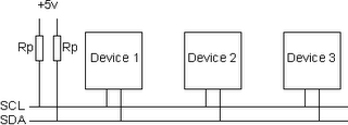
I²C bus (Inter-Integrated Circuit) is a bidirectional, half duplex, two-wire, synchoronous bus, originally designed for interconnection over short distances within a piece of equipment. The I2C bus uses two lines called Serial Clock Line (SCL) and Serial Data Lines (SDA). Both lines are pulled high via a resistor (Rpu) as shown in Figure below. The bus is defined by Philips, see more details . Three speed modes are specified: Standard; 100kbps [Bits per Second], Fast mode; 400kbps, High speed mode 3.4Mbps. I2C, due to its two-wire nature (one clock, one data) can only communicate half-duplex. The maximum bus capacitance is 400pF, which sets the maximum number of devices on the bus and the maximum line length. The interface uses 8 bit long bytes, MSB (Most Significant Bit) first, with each device having a unique address. Any device may be a Transmitter or Receiver, and a Master or Slave. The Slave is any device addressed by the Master. A system may have more than one Master, although o...

8051 Development Setup: Final test

Execute MIDE-51.exe and File-->New (Ctrl+N), edit this code #include "p89v51rd2.h" unsigned char i; void main() { i=10; } Save to anyname.c and then Build (F9). You will found many files in the directory, one of them is .HEX file which can be downloaded to your MCU by using FlashMagic. Or, you can simulate it by using Jsim51, Build and Sim (Shift+Ctrl+F9). Note: I tested on my P89V51RD2 MPU. Enjoy your 8051 microcontroller.