Posts

Enjoy HD in OLD laptop in 20$

As i came across the news of the release of The BCM70010/BCM70012 chipset ...i am very excited to revive my P4 pc .. What is this chip and how it is useful : Broadcom chip uses Crystal HD Enhanced Video Accelerator solution. So your old laptop/PC or even ARM miniPCI devices you can revive with a card that has this chip. Most interesting part is the cost just 20$ These are selling via ebay India: http://cgi.ebay.in/ws/eBayISAPI.dll?ViewItem&item=320436937576 or you can try ebay.com if you have paypal. This introduces the advantages of next-generation high definition H.264 and VC-1 video compression algorithms to netbook and nettop applications like the playback of streaming media and downloaded media as well as Blu-ray™ discs. The chipset is a single-stream HD AVC/VC-1/MPEG-2 decoder solution capable of full HD real-time decoding. The high performance and low power consumption of the solution allow reduced CPU utilization and support for mobile platform designs. The chips...

My Hot Air Pencil in Rs 300 for smd

Image
ARM9 soldering problem is solved.. i made the hot air pencil. See pics and details are ... Parts needed : 1 cheap soldering pipe shaped ,coil heater type:140/- like this http://www.hvwtech.com/products/206/44100_PV.jpg 1acqurium pump + air pipe :130/- 6 inch pneumatic tubing :30/- like this http://ecx.images-amazon.com/images/...500_AA280_.jpg (my innovation it withstands approx 100deg, at the coupling end the temp does not go v high). Super glue , paper etc.. How to : 1.rip apart soldering iron, remove metal tip. 2.Leaving the front hole (where metal tip was there) cover the other holes with 2 layer of paper put duct tape to make the paper hold.This is to prevent air leak. 3. connect air pipe to the 6" pneumatic tubing seal the joint with superglue,put the other end of the tubing to soldering iron metal pipe. with paper as insulator. 4. Close the soldering handle with pipe and wires mine is taped to hold together."Be careful not to short mains wires".My iron had fully i...

ARM9 Board Taking shape -2:Active parts

Image
See the power IC how small it is , I will have to make a HOT AIR PENCIL. There are 20+ web sites detailing it but I will use my way to do that.. Done the shopping by now. I will create a post on the same soon.

LED desktop thingy!

Image
I bought a china made LED torch cum table lamp. Costed very less. Charges well gives 8Hour backup minimum(did not check when it goes off) from a 6hour charge What is special here is it is a torch with a flip 6ultrabright LED panel.The panel tilts at 15degrees , so you can point the LED sets all directions... that is too much the price of 1 cup coffee in some places .Panel can be hidden when used as torch. But there is a problem! The table light /torch loses the intensity after 3hours to 60%. There must be a way to keep intensity same. I needed a constant current source at least 0.5A. I searched on net and got (LED driver) : http://www.candlepowerforums.com/vb/showthread.php?t=236260 image: And I know about joule thief circuit ->simple 1 or 2 transistor circuit increases the voltage. Here is joule thief: (i assume battery is 6v ) Plan is : battery(6v)>joule thief(9v)>LED driver>LEDs smooth white light till battery loses the charge (if backup become 6Hrs , fine na!)

Arm9 board free samples locked up

Image
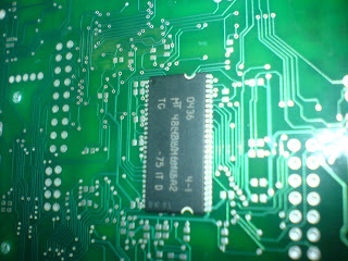
I am asking free samples from a company , for atleast the power section some one named Srikanth G. from their local office ,locking the samples and asking business details again and again . Samples save good $$$. If not i have 10 other alternatives. Letz see what comes out . Board is in progress , 90% of components supply i sorted out. The At01 series has inbuilt loader that will init the chip and peripherials. Now i need to learn the 1st time flashing of the Uboot loader. SD RAM I got : see it on the board before soldering Update: sample will be most probably be released , as i convinced them . Local center guy i forced putting mail to HO. hahaha :). One problem is there: The SDRAM pads are too small ,go under the chip legs.manual soldering will be tricky. UPDATE: IC Pack and samples have arrived , flash,eeprom,power sections things came . from usa, mainchip and ethernet chip has to come from Taiwan and Hong Kong. Look at the Flash IC box , well packed in antistatic box ...

ARM9 BOARD TAKING SHAPE-2 :passives

Image
This is phase 1: I am at my office where i work as consultant ..whoa !today passive components have arrived.Means the resistor and capacitors 0402size. The size presented a hurdle, 0603 components are pretty easy to get . But finally i got hold of the components. more are there in my tray shelf . I got passive s for 10 boards for trial build we will take chips 1 pc each . Let the prototype be ready as well toolset .. then may go bulk. phases of build : Phase 1: Passives arrives + jacks etc {done} Phase 2: Active cmp arrives mainly At91rm9200 Phase 3: Solder and test

ARM9Board ...taking shape 1

Image
The ARM9 board taking shape , at office I got a delivery of 20 PCBS recently... well built FR4 laminate .Green masking applied on both sides , Silver coated pads and vias . Thanks to my contacts in product industry .. However the sourcing of the chips is still critical .I am working on it So far i have been in touch with many middleman Letz wait and see...

My ARM9 Development board for indian developers

Image
The Low Cost ARM9 board is here . I always wanted to bring a low cost solution for indian developers . A highly capable ARM9 board that can run embedded realtime linux . with ample amount of memory and provision for future expansion. Now! Why to pay 40 k for an ARM lab setup with JTAG and all ...my design is just The design criteria is fulfilled with AT91RM series ARM9 chip based design . Added 256MB sdRAM,64MB flash,24LC512 eeprom, can, JTAG , USB serial interface( for laptops this is handy as there is no serial port ), CAN bus transiever, controller . It has a USB host too! there are more interfaces can be added . There are many online ported versions of linux for the chips as well as develeoper forums /Groups . Designed during off time and now almost ready : See the snaps of it : After working 4 years in embedded product domain , i felt the need of hardware test setup for learning board level porting, device drivers BSP development. As well as a board that is suitable for my...

Design your own PCB web tutorial

Image
Avoid bird nest design for your boards ! Just get a PCB made , the first step is design ... It is not as hard as you might think: download : Eagle PCB editor it is free ,but 1 limitation i.e board size, as long as you make smaller boards. And instead of writing full tutorial i am gving links to online tutorials: It is by sparkfun .com ..a part of the tutorials designed for new builder of electronics circuits sparkfunPCB Tutorial

Books for ARM processor programming

Image
Why to learn ARM ? ARM is the most popular of leading cores of the embedded processors. it is designed for the specific clients and for different product demands the processor is added with extra feature. there is always high demand of skilled manpower who has worked with arm processor and embedded linux . I recommend few books here you can get as ebooks ,but getting a printed copy is better and you will get a faster /regular learning from it ..may need to refer the books in later part of your career. All big giants like sony ,honeywell,philips,nokia,siemens ,HP work on these ARM core based products. 1) ARM System-on-Chip Architecture (2nd Edition) Desc:The future of the computer and communications industries is converging on mobile information appliances - phones, PDAs, laptops and other devices. The ARM is at the heart of this trend, leading the way in system-on-chip (SoC) development and becoming the processor core of choice for many embedded applications. System-on-chip techn...

+ - 15 V regulated power supply

Image
This is useful for small amplifier , op amp projects Parts : IC 7815,7915 -1 nos , 2200uf 35 V - 2 nos .22uf ceramic/ poly - 2 nos 100uf 25v -2 nos Verro board -1 no Transformer 12v -0-12v secondary and 220v /110 V primary wires for connecting etc

Which controller to go for ATMEL AVR,PIC,ARM?

For basic usage 8051 is powerful enough for your needs . But if you want to serious stuff like LCD touchscreen ethernet usage ,CMOS sensors then ARM based architectures for a number of reasons: * They are dropping Al most the same as other low end boards * They are FULLY 32-bit cores, 8-bit MCU's just don't cut it some times. For example my DVD player from 2002 has an 8052 MCU embedded in it as a front end (remote control reading, On Screen Display etc.). But newer DVD players from what I've been seeing are either using proprietary cores or ARM based cores. * Also budget wireless chipsets and routers use ARM7 and ARM9 chips (probably to do the WEP/WPA encryption). Well I do know the wifi chipset in the PSP uses an ARM9 based CPU. * Supported by freeware GNU compilers (GCC for example), makes development rather painless and if you want to code in assembly (GNU assembler really sucks ) then you get free assembler. * Tons of very cheap devkits available (t...

Building DIY enclosure -Part2:body

Image
Here we make an cool looking enclosure with body part from a HDD (external) casing.Something like this steps: 1.If more height is needed Cut the Enclosureas in pic ..separate top and bottom plates 2.fit 2 pieces of MDF ,spraypainterd with aerosol can(very cheap 5$). 3.Drill screw holes with 1$ hand drill on the sides and weo have completed the body for front you can use aluminum or acrylic piece(easy to cut).See pics below...

SMD Soldering at home

Image
Most hobbyists are working on small kits layouts .And prefer the through hole parts.After the projects id done the board looks bulky and needs more space to fit. Never possible to make card size boards... build needs lott of wiring and connecting wires . I suggest why not explore SMD.Yes sourcing components is an issue ,you can use sites like mouser.com for parts .. before getting into details lets learn Smd soldering at home. Here are some videos you can refer: open youtube go through related videos ! Tools needed , just tweezers , and a fine tip soldering iron,and a liquid flux. For pcb try iron on pcb fabrication.

Auzentech X-FI Home Theater 7.1 HDMI 1.3 Combo card

Image
Many audio video enthusiasts are looking forward to full 8 Channel lossless high resolution audio that delivers all the original audio content recorded and meant to be heard by the end users. Auzentech recently launched a new HDMI 1.3 combo card in their high end card line up .Whats unique in this card is supports full HDMI 1.3 high resolution audio standards such as Dolby® Digital Plus, Dolby® Digital TrueHD, DTS-HD and Bit streaming with Non Down-Sampling Output capabilities. Card features are very impressive: Blu-ray support via Cyberlink's latest PowerDVD application (available separately) Support for PCM 8 channel, 24-bit/192kHz 24p True Cinema Output Blu-ray Audio with no downsampling High bit-rate audio, such as Dolby TrueHD, DTS-HD Master Audio bitstream Dolby Digital Live for Windows and Vista DTS Neo:PC & DTS Interactive for Windows Vista EAX Advanced HD 5.0 NVidia and CyberLink have both joined Auzentech on this project to ensure a full HDMI 1.3 solution via hardw...

How to connect HTPC to AVR

Image
The home theatre PC(HTPC) is immersing as a common entertainment platform.The HTPCs today are equipped with best video audio chips ...connection possibilities,remote etc making it part of AV gear for living room. There are different possibilities of getting video and audio from htpc to LCD tv /HD plasma and 5.1 dedicated speakers . Option one: Feed audio directly to AVR(Audio Video) Reciever with SPDIF optical.. depending on the motherboard the audio will be dolby encodede/dtd pass through or just 2 channel. Video just connect to LCD with HDMI>DVI adapter (very cheap one). Cons: you cant switch video source unless you have a manual DVI switch Option Two : Add a graphics card such as ATI 4650 HDMI,You will be able to get 48 Khz 16 Bit 7.1 Channel PCM audio with that. some say If you are not using HDMI exclusively, you are not “using your connection options the best way possible” . Option three: If you use devices like PS3,HTPC,HDMI dvd players buy a device like XCM

LCD panel

Image
LCD panel making Idea 1> Take acrylic ,cut with a hand drill used for PCB drilling 2> File the cut to smoothness 3> for that rough outer ,cut the sheet from back of corporate diary/premium notebook Done!

LED effect with micro 89c51

Image
Pretty simple LED effect with a simple code and schematic #include #define first P1 #define second P2 //sbit first P1^0 //sbit second P2^0 void wait() { int i,j; for(i=0;i for(j=0;j } main() { unsigned int i; /* Delay var */ unsigned char j,m; /* LED var */ while (1) { for(m=0x01;m!=0xff;m=m(m { for(i=1;i { /* Loop forever */ for (j=m; j!= 0x00; j P1 = j; /* Output to LED Port */ wait (); /* call wait function */ } P1=0; for (j=m; j!=0x00; j P2 = j; /* Output to LED Port */ wait (); } /* call wait function */ P2=0; } } } } schematic : Quickpost this image to Myspace, Digg, Facebook, and others!
Image
schematic Quickpost this image to Myspace, Digg, Facebook, and others! code working: If you press any button in the matrix keyboard it controller will scan the corresponding ascii code that will send serially to the port pin specified . Corresponding ascii code we can see in LED blinkings. #include /* add the headers here */ #define COL P2 #define ROW P1 void msdelay(unsigned int value); void sertx(unsigned char); unsigned char keyboard[4][4]={ '7','8','9','/', '4','5','6','*', '1','2','3','-', 'a','0','=','+' }; void main() { unsigned char colloc,rowloc; TMOD=0x20; TH1=-24; SCON=0x50; TR1=1; COL=0xff; while(1) { do { ROW=0x00; colloc=COL; colloc&=0x0f; } while(colloc!=0x0f); do { do { msdelay(20); colloc=COL; colloc&=0x0f; }while(colloc==0x0f); msdelay(20); colloc=COL; colloc&=0x0f; } while(colloc==0x0f); while(1) { ROW=0xfe; colloc=COL; colloc...

Cool front panel for DIY projects -part1

Image
After long break i am back again ..this time for all hobbyists,DIY people I am adding some tricks for making a front panel . Step1: Backlit Logo Devices like amplifier , D/a converter need a logo panel ...why to put poor looking popping out led,with a paper sticker below? Here we go : 1.Print 2 copies of same logo text on butter paper ,letters white,rest black 2.stick them together,to make dark areas dark 3.put smd (surface mount) behind the panel Result? See the pic above... If you still wanna do a lil more fancy designs.. add a weavy led circuit with IC 4017..may look even cooler!